Mixed voltage interfacing for design or hacking

Modern digital systems involve a wide array of voltages. Instead of just the classic 5V TTL, they now use components and busses ranging from 3.3V down to 1.0V. Interfacing with these systems is tricky, especially when you have multiple power sources, capacitive loads, and inrush current from devices being powered on. It’s important to understand the internal design of all drivers, both in your board and the target, to be sure your final product is cheap but reliable.

When doing a security audit of an embedded device, interfacing is one of the main tasks. You have to figure out what signals you want to tap or manipulate. You pick a speed range and signal characteristics. For example, you typically want to sample at 4x the target data rate to ensure a clean signal or barring that, lock onto a clock to synchronize at 1x. For active attacks such as glitching, you often have to do some analog design for the pulse generator and trigger it from your digital logic. Most importantly, you have to make sure your monitoring board does not disrupt the system. The Xbox tap board (pdf) built by bunnie is a great case study for this, as well as his recent NeTV device.

Building a mass market board is different than a quick hack for a one-off review, and cost becomes a big concern. Sure, you can use an external level shifter or transceiver chip. However, these come with a lot of trade-offs. They add latency to switching times. They often require dual power supplies, which may not be available for your particular application. They usually require extra control pins (e.g., to select signal direction). They force you to switch a group of pins all at once, not individually. Most importantly, they add cost and take up board space. With a little more thought, you can often come up with a simpler solution.

There was a great article in Circuit Cellar on mixed-voltage digital interfacing. It goes into a lot of the different design approaches, from current-limiting resistors all the way up to BJTs and MOSFETs. The first step is to understand the internals of I/O pins on most digital devices. Below is a diagram I reproduced from the article.

CMOS I/O pin, showing internal ESD diodes

Whether you are using a microcontroller or logic chip, usually the I/O pins have a similar design. The input to the gate is protected by diodes that will conduct current to ground if the input voltage goes more negative than the GND pin or to Vcc if the input is more positive than Vcc. These diodes are normally used to protect against static discharge, but can also be a useful part of your design if you are careful.

The current limiting resistor can be calculated by figuring out the maximum and minimum voltages your input will see and the maximum current flow you want into your device. You also have to take into account the diode’s voltage drop. Here’s an example calculation:

Max input level: 6V
Vcc: 5V
Diode drop: 0.7V (typical)
Max current: 100 microamps

R = V / I = (6 – 5 – 0.7) / 0.0001 = 3K ohms

While microcontrollers and 74xx logic devices are often tolerant of some moderate current, FPGAs are extremely sensitive. If you’re using an FPGA, use a level shifter chip or you’ll be sorry. Also, most devices are more sensitive to negative voltage than positive. Even if you’re within the specs for max current, a negative voltage may quickly lead to latch-up.

Level shifters usually take in dual voltages and safely isolate both sides. Some are one-way, which can be used as line drivers or line receivers. Others are bidirectional transceivers, and the direction is selected by an extra pin. If you can’t afford the extra pins, you can often combine an open-collector transmitter with a line receiver. However, if you happen to drive the lines by transmitting at the same time as the other side, you can fry your chips.

To summarize, mixed voltage interfacing is a skill you’ll need when building your own devices or hacking existing ones. You can get by with just a current-limiting resistor in many cases, but be sure you understand the I/O pin design to avoid costly failures, especially in the field over time. For more assurance or with sensitive parts like FPGAs, you’ll have to use a level shifter.

The Magic Inside Bunnie’s New NeTV

A year ago, what was probably the most important Pastebin posting ever was released by an anonymous hacker. The HDCP master key gave the ability for anyone to derive the keys protecting the link between DVD players and TVs. There was no possibility of revocation. The only remaining question was, “who would be the first to deploy this key in an HDCP stripper?”

Last week, the HDCP master key was silently deployed, but surprisingly, not in a stripper or other circumvention device. Instead, it’s enabling a useful new system called the Chumby NeTV. It was created by Bunnie Huang, who is known for inventing the Chumby and hacking the Xbox. He’s driving down the cost of TV-connected hardware with a very innovative approach.

The NeTV displays Internet apps on your TV. You can see Twitter feeds, view photos, and browse the web via an on-screen display. It overlays this information on your video source. You can control it from your iPhone or Android phone. It’s simple to install since you merely plug it inline with your cable box or DVD player’s HDMI connection to the TV. And in true Bunnie fashion, the hardware and software is all open source.

When I first heard of this last week, I didn’t think much of it. It’s a neat concept, but I don’t have an HDTV. Then, a friend contacted me.

“Have you figured out how the NeTV works? There’s a lot of speculation, but I think I’ve figured it out,” he said. I told him I hadn’t thought much about it, then downloaded the source code to the FPGA to take a look.

I was surprised to find an entire HDCP implementation, but it didn’t quite make sense. There was no decryption block or device keys. I emailed Bunnie, asking how it could do alpha blending without decrypting the video. He wrote back from a plane in Tokyo with a cryptic message, “No decryption involved, just chroma key.”

This was the hint I needed. I went back and watched the demo video. The overlay was not transparent as I had first thought. It was opaque. To do alpha blending, you have to have plaintext video in order to mask off the appropriate bits and combine them. But to apply an opaque overlay, you could just overwrite the appropriate video locations with your substituted data. It would require careful timing, but no decryption.

Chroma key (aka “blue/green screen”) uses color for in-band signaling. Typically, an actor performs in front of a green screen. A computer (or a filter, in the old days) substitutes data from another feed wherever there is green. This is the foundation of most special effects in movies. Most importantly, it is simple and can be performed quickly with a minimum of logic.

The NeTV generates its output signal by combining the input video source and the generated overlay with this same technique. The overlay is mostly filled with pixels of an unusual color (Bunnie called it “magic pink”). The FPGA monitors the input signal position (vertical/horizontal sync, which aren’t encrypted) to know where it is within each frame of video. When it is within the pink region of the overlay, it just passes through the encrypted input video. Otherwise, it displays the overlay. The HDCP implementation is needed to encrypt the overlay, otherwise this part of the screen will be scrambled when the TV tries to decrypt it. But, indeed, there is no decryption of the input content.

This is impressive work, on par with the demoscene. The NeTV synchronizes with every frame of video, no jitter, choosing which pixel stream to output (and possibly encrypt) on-the-fly. But there’s more.

To generate the keystream, the NeTV has to synchronize with the HDCP key exchange between video source and TV. It replicates each step of the process so that it derives the correct stream key. To keep any timing issues with the main CPU from delaying the key exchange, it resets the link after deriving the shared key to be sure everything is aligned again. Since the transport key only depends on the two endpoint device keys, the same shared key is always used.

This is extremely impressive from a technical standpoint, but it’s also interesting from a content protection standpoint. The NeTV has no device keys of its own; it derives the ones in use by your video source and TV as needed. It never decrypts video, only encrypts its on-screen display to match. It can’t easily be turned into an HDCP stripper since that would require a lot of rework of the internals. (The Revue, with its HDMI transceiver chip and Atom processor could probably be turned into an HDCP stripper with a similar level of effort.)

Bunnie has done it again with a cheap device that applies his extensive creativity to not just solve a problem, but do it in style. Whatever the outcome of his maverick engineering is in the marketplace, the internals are a thing of beauty.

Building a USB protocol analyzer

The recent effort by bushing‘s team to develop an open-source USB protocol analyzer reminded me of a quick hack I did previously. I was debugging a tricky USB problem but only had an oscilloscope.

If you’ve been following this blog, you know one of my hobby projects has been designing a USB interface for old Commodore floppy drives. The goal is to archive old data, including the copy-protection bits, before the media fails. Back in January 2009, I was debugging the first prototype board. Most of the commands succeeded but one would fail immediately every time I sent it.

I tried a software USB analyzer, but it didn’t show any more information. The command was returning almost immediately with no data. Debugging output on the device’s UART didn’t show anything abnormal, except it was never receiving the problem command. So the problem had to be between the host and target’s USB stacks, and possibly was in the AVR‘s hardware USB state machine. Only a bus analyzer could reveal what was going on.

Like other hobby developers, I couldn’t justify the cost of a dedicated USB analyzer just to troubleshoot this one problem, especially in a design I would be releasing for free. Since I did have an oscilloscope at work, I decided to build a USB decoding stack on top of it.

USB, like Ethernet and TCP/IP, is a combination of protocols. The lowest layer is the physical cabling and bit signalling. On top of this is packet framing and device addressing. Next, each device has a set of endpoints. These are analogous to TCP/UDP ports and support control, bulk, or interrupt message types. The standard control endpoint (address 0) handles a set of common configuration messages. Other endpoints are device-specific.

High-speed signalling (480 Mbit/s) is a bit different from full/low-speed, so I won’t describe it here. Suffice to say, you can just put a USB 1.1 hub between your device and host to force it to downgrade speeds. Unless you’re trying to debug a problem with high-speed signalling itself, this is sufficient to debug protocol-level issues.

The USB physical layer uses differential current flow to signal bits. This balances the charge, decreasing the latency for line transitions and increasing noise rejection.  I hooked up probes to the D+ and D- lines and saw a trace like this:

Each zero bit in USB is signalled by a transition, low to high or high to low. A one bit is signalled by no transition for the clock period. (This is called NRZI encoding). Obviously, there’s a chance for sender and receiver clocks to drift out of sync if there are too many one bits in a row, so a zero bit is stuffed into the frame after every 6 one bits. It is discarded by the receiver. An end-of-packet is signalled by a single-ended zero (SE0), which is both lines held low. You can see this at the beginning of the trace above

To start each packet, USB sends an 0x80 byte, least-significant bit first. This is 7 transitions followed by a one bit, allowing the receiver to synchronize their clock on it. You can see this in the trace above, just after the end-of-packet from the previous frame. After the sync bits, the rest of the frame is byte-oriented.

The host initiates every transaction. In a control transfer, it sends the command packet, generates an optional data phase (in/out from device), and ends with a status phase. If the transaction failed, the device returns an error byte.

My decoding script implemented all the layers in the quickest way possible. After taking a scope trace, I’d dump the samples to a file. The script would then run through them, looking for the first edge. If this edge was part of a sync byte, it would begin byte-aligned decoding of a frame to pass up to higher-level functions. At the end of the packet, it would go back to scanning for the next edge. Using python’s generators made this quite easy since it was just a series of nested loops instead of a complicated state machine.

Since this was a quick hack, I cut corners. To detect the SE0 end-of-packet, you really need to monitor both D+ and D-. At higher speeds, the peaks get lower since less current is exchanged. However, at lower speeds, you can ignore this and just put a scope probe on the D- line. Instead of proper decoding of the SE0, I’d just decode each frame until no more data was expected and then yield a fake EOP symbol to the upper layers.

After a few days of debugging, I found the problem. The LUFA USB stack I was using in my firmware had a bug. It had a filter for standard control messages (such as endpoint configuration) that it handled for you. Class-specific transactions were passed up to a handler in my firmware. The bug was that the filter was too permissive — all control transfers of type 6, even if they were class-specific, were captured by LUFA. This ended up returning an error without ever passing the message to my firmware. (By the way, the LUFA stack is excellent, and this bug has long since been fixed).

Back in the present, I’m glad to see the OpenVizsla project creating a cheaper USB analyzer. It should be a great product. Based on my experience, I have some questions about their approach I hope are helpful.

It seems kind of strange that they are going for high-speed support. Since the higher-level protocol messages you might want to reverse-engineer are the same regardless of speed, it would be cheaper to just handle low/full speed and use a hub to force devices to downgrade. I guess they might be dealing with proprietary devices, such as the Kinect, that refuse to operate at lower speeds. But if that isn’t the case, their namesake, the Beagle 12, is a great product for only $400.

I have used the Total Phase Beagle USB analyzers, and they’re really nice. As with most products these days, the software makes the difference. They support Windows, Mac, and Linux and have a useful API. They can output data in CSV or binary formats. They will be supporting USB 3.0 (5 Gbps) soon.

I am glad OpenVizsla will be driving down the price for USB analyzers and providing an option for hobbyists. At the same time, I have some concern that it will drive away business from a company that provides open APIs and well-supported software. Hopefully, Total Phase’s move upstream to USB 3.0 will keep them competitive for people doing commercial development and the OpenVizsla will fill an underserved niche.

Building the ZoomFloppy slides

At ECCC 2010, I presented these slides on the ZoomFloppy, a new device for accessing Commodore floppy drives from a PC via USB. The firmware, known as xum1541, has been available since fall 2009 for those who want to build their own board, but the ZoomFloppy is the first device that will be a complete product offered for sale. Jim Brain will be manufacturing and selling it by the end of the year.

The ZoomFloppy has a number of features beyond simple disk access, which is implemented in OpenCBM. It can also nibble protected disks using a parallel cable and nibtools. It is software-upgradeable and this presentation discusses some features that are planned for the future.

One surprising finding I made was that by running the 1571 drive in double-clocked (2 MHz mode), the hardware UART is just fast enough to enable transfer of raw bits, directly off the media. No one has every created a copier that took advantage of this “hidden” mode in the 25 years since the 1571 was introduced. Normally, this kind of transfer requires soldering a parallel cable into your drive. This mode works via the normal serial cable, but requires low-latency control of the bus that is only possible with a microcontroller (not DB25 printer port).

I also discuss how modern day piracy on the PS3 affected our chip supply and digress a bit to discuss old copy protection schemes. I hope you enjoy the presentation.

(Direct pdf download)

A new direction for homebrew console hackers?

A recent article on game console hacking focused on the Wii and a group of enthusiasts who hack it in order to run Linux or homebrew games. The article is very interesting and delves into the debate about those who hack consoles for fun and others who only care about piracy. The fundamental question behind all this: is there a way to separate the efforts of those two groups, limiting one more than the other?

Michael Steil and Felix Domke, who were mentioned in the article, gave a great talk about Xbox 360 security a few years ago. Michael compared the history of Xbox 360 security to the PS3 and Wii, among other consoles. (Here’s a direct link to the relevant portion of the video). Of all the consoles, only the PS3 was not hacked at the time, although it has since been hacked. Since the PS3 had an officially supported method of booting Linux, there was less reason for the homebrew community to attack it. It was secure from piracy for about 3 years, the longest of any of the modern consoles.

Michael’s claim was that all of the consoles had been hacked to run homebrew games or Linux, but the ultimate result was piracy. This was likely due to the hobbyists having more skill than the pirates, something which has also been the case in smart phones but less so in satellite TV. The case of the PS3 also supports his theory.

Starting back in the 1980’s, there has been a history of software crackers getting jobs designing new protection methods. So what if the homebrew hackers put more effort into protecting their methods from the pirates? There are two approaches they might take: software or hardware protection.

Software protection has been used for exploits before. The original Xbox save game exploit used some interesting obfuscation techniques to limit it to only booting Linux. It stored its payload encrypted in the JPEG header of a penguin image. It didn’t bypass code signature verification completely, it modified the Xbox’s RSA public key to have a trivial factor, which allowed the author to sign his own images with a different private key.

With all this work, it took about 3 months for someone to reverse-engineer it. At that point, the same hole could be used to run pirated games. However, this hack didn’t directly enable piracy because there were already modchip-based methods in use. So, while obfuscation can add some time to pirates getting access to the exploit, it wasn’t much.

Another approach is to embed the exploit in a modchip. These have long been used by pirates to protect their exploits from other pirates. As soon as another group clones an exploit, the price invariably goes down. Depending on the exploitation method and protection skill of the designer, reverse-engineering the modchip can be as hard as developing the exploit independently.

The homebrew community does not release many modchips because of the development cost. But if they did, it’s possible they could reduce the risk of piracy from their exploits. It would be interesting to see a homebrew-only modchip, where games were signed by a key that certified they were independently developed and not just a copy of a commercial game. The modchip could even be a platform for limiting exploitation of new holes that were only used for piracy. In effect, the homebrew hackers would be setting up their own parallel system of control to enforce their own code of ethics.

Software and hardware protection could slow down pirates acquiring exploits. However, the approach that has already proven effective is to limit the attention of the homebrew hackers by giving them limited access to the hardware. Game console vendors should take into account the dynamics of homebrew hackers versus the pirates in order to protect their platform’s revenue.

But what can you also do about it, homebrew hackers? Can you design a survivable system for keeping your favorite console safe from piracy while enabling homebrew? Enforce a code of ethics within your group via technical measures? If anyone can make this happen, you can.

Why digital logic is different than analog (part 2)

Last time, we asked the question “What is the difference between analog and digital logic?” We identified two areas: noise and dynamic range. The latter limitation is that you can’t have an infinite (or even very high) voltage, so analog logic will always have some maximum value it can represent. With digital logic, you just add more bits to your representation and you can instantly increase the range. This time, we’ll consider noise and analog computers.

The first computers were analog. One of the initial applications was to calculate artillery trajectories under different conditions. The old way to fire a gun was to measure the wind (strength and direction), distance, and elevation to the target, and then look up a number in a table to get the appropriate angle. Originally these tables were generated by test-firing guns and then deriving the variations with calculations done by hand. People who did this work were known as “computers”.

Analog electronic computers were applied to this task in World War 2. This kind of computer worked with a continuously varying voltage, using op-amps to calculate sums and differences of values. The advantages are that the results are highly accurate and computation is very fast. An analog computer does not suffer from the quantization problem or aliasing because the signal is continuous, not discrete like digital sampling.

We’d still be using analog computers today if it wasn’t for noise. The same advantages to working with a continuous analog signal mean it is vulnerable to cascading noise. On every pass through an op-amp, a small amount of noise is added. At some point, the signal is not recoverable from the noise and the calculation can’t proceed. Much of the more recent work on analog computers seems to be focused on filtering noise.

As we saw last time, there is no such thing as a purely digital computer. “Digital” is a point-of-view, a way of interpreting an analog signal of some kind. This is both simple and sublime. It means that we can overcome the advantages inherent in our analog world by moving up a level of abstraction — manipulating symbols and abstract logic instead of concrete and continuous substances such as a voltage.

Digital logic was designed to have the regenerative property. What this means is that each stage of processing starts over from scratch, generating its own signal that was only dependent on the meaning of the previous stages of logic and its computational result. The key thing to understand here is that it is not amplifying the input signal directly, it is regenerating the output by switching a set of transistors. This means that digital logic stages can be infinitely deep and the signal at the end is as free of noise as it was at the start.

To maintain the regenerative property, several rules have to be followed. Since transistors work with continuous voltages and can be considered an analog component, digital logic rules state how they must be used. Each type of silicon family (CMOS, TTL, LVTTL, ECL, GTL) has its own particular rules. One set of rules deals with timing — how fast the input voltages can change and how long they have to remain at a given level to be registered as a logical 1 or 0. Another rule gives the voltage levels for outputing or receiving a logical 1 or 0.

The rules for input and output voltage levels differ, which is key to noise rejection. To maximize noise rejection, you want your output levels to be as far apart as possible but your input levels closer. This handles noise created by behavior such as ground bounce. If your input levels are too close together though, you’ll get false readings due to noise or intermediate input voltages (low slew rate). The difference between logical 1 and 0 is called the noise margin and is measured in volts.

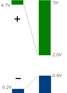
Here are the specified voltage levels for TTL. Output is on the left:

Output and input TTL levels

The diagram shows that outputs must have at least a 4.5V difference between logic levels and the inputs have a 1.2V difference. For example, if you have a noisy input when the sender transitions to logical 0 but the noise peaks are less than 0.8V, you’ll still get a clean logical 0 from the output (0.2V or less).

Manufacturers design these tolerances into their components. If you also follow the timing rules, your digital logic will have all the desired properties: noise rejection, the regenerative property, and arbitrarily large dynamic range. This is what people actually mean when they talk about the reliability of digital data and processing.

By the way, different logic families have different thresholds. The output response over a continuously varying input voltage is called the voltage transfer characteristic. It indicates the S-curve of output voltage for a gate as the input varies. Another way of interpreting the above diagram is that by staying to the far left or right of this curve, we avoid the transition region and thus can reject more noise.

It’s often enlightening to step back and consider the assumptions underlying our everyday work. Given that we live in an analog world, I find the ideas and unique guarantees digital logic provides fascinating.