Why digital logic is different than analog (part 2)

Last time, we asked the question “What is the difference between analog and digital logic?” We identified two areas: noise and dynamic range. The latter limitation is that you can’t have an infinite (or even very high) voltage, so analog logic will always have some maximum value it can represent. With digital logic, you just add more bits to your representation and you can instantly increase the range. This time, we’ll consider noise and analog computers.

The first computers were analog. One of the initial applications was to calculate artillery trajectories under different conditions. The old way to fire a gun was to measure the wind (strength and direction), distance, and elevation to the target, and then look up a number in a table to get the appropriate angle. Originally these tables were generated by test-firing guns and then deriving the variations with calculations done by hand. People who did this work were known as “computers”.

Analog electronic computers were applied to this task in World War 2. This kind of computer worked with a continuously varying voltage, using op-amps to calculate sums and differences of values. The advantages are that the results are highly accurate and computation is very fast. An analog computer does not suffer from the quantization problem or aliasing because the signal is continuous, not discrete like digital sampling.

We’d still be using analog computers today if it wasn’t for noise. The same advantages to working with a continuous analog signal mean it is vulnerable to cascading noise. On every pass through an op-amp, a small amount of noise is added. At some point, the signal is not recoverable from the noise and the calculation can’t proceed. Much of the more recent work on analog computers seems to be focused on filtering noise.

As we saw last time, there is no such thing as a purely digital computer. “Digital” is a point-of-view, a way of interpreting an analog signal of some kind. This is both simple and sublime. It means that we can overcome the advantages inherent in our analog world by moving up a level of abstraction — manipulating symbols and abstract logic instead of concrete and continuous substances such as a voltage.

Digital logic was designed to have the regenerative property. What this means is that each stage of processing starts over from scratch, generating its own signal that was only dependent on the meaning of the previous stages of logic and its computational result. The key thing to understand here is that it is not amplifying the input signal directly, it is regenerating the output by switching a set of transistors. This means that digital logic stages can be infinitely deep and the signal at the end is as free of noise as it was at the start.

To maintain the regenerative property, several rules have to be followed. Since transistors work with continuous voltages and can be considered an analog component, digital logic rules state how they must be used. Each type of silicon family (CMOS, TTL, LVTTL, ECL, GTL) has its own particular rules. One set of rules deals with timing — how fast the input voltages can change and how long they have to remain at a given level to be registered as a logical 1 or 0. Another rule gives the voltage levels for outputing or receiving a logical 1 or 0.

The rules for input and output voltage levels differ, which is key to noise rejection. To maximize noise rejection, you want your output levels to be as far apart as possible but your input levels closer. This handles noise created by behavior such as ground bounce. If your input levels are too close together though, you’ll get false readings due to noise or intermediate input voltages (low slew rate). The difference between logical 1 and 0 is called the noise margin and is measured in volts.

Here are the specified voltage levels for TTL. Output is on the left:
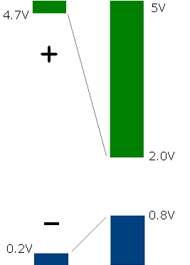
Output and input TTL levels

The diagram shows that outputs must have at least a 4.5V difference between logic levels and the inputs have a 1.2V difference. For example, if you have a noisy input when the sender transitions to logical 0 but the noise peaks are less than 0.8V, you’ll still get a clean logical 0 from the output (0.2V or less).

Manufacturers design these tolerances into their components. If you also follow the timing rules, your digital logic will have all the desired properties: noise rejection, the regenerative property, and arbitrarily large dynamic range. This is what people actually mean when they talk about the reliability of digital data and processing.

By the way, different logic families have different thresholds. The output response over a continuously varying input voltage is called the voltage transfer characteristic. It indicates the S-curve of output voltage for a gate as the input varies. Another way of interpreting the above diagram is that by staying to the far left or right of this curve, we avoid the transition region and thus can reject more noise.

It’s often enlightening to step back and consider the assumptions underlying our everyday work. Given that we live in an analog world, I find the ideas and unique guarantees digital logic provides fascinating.
Why digital logic is different than analog

I occasionally come across a concept that, while obvious to those who know it, isn’t as widely spread as it should be. One such question is, “What is the difference between analog and digital logic?” There are a lot of people that know the answer in an abstract way, but the real distinction is both simple and sublime.

The abstract answer is that an analog signal is continuous while a digital signal is discrete, ones and zeros. When people think of analog technology, a common example is cassette tape, hissing and popping, compared to the relative clarity of a CD or MP3. The common sense reason given why the digital version sounds better is because the ones and zeros are conceptually perfect, matching the original recording. Also, copies are perfect as well because the ones and zeros can be exactly duplicated.

However, this explanation begins to break down when you consider it closely. Due to the quantization problem, each digital representation (sample) of the waveform at a moment in time is inexact because you can always divide it into smaller and smaller parts. So an analog signal at one point in time is more perfect than its digital sample. Also, the lower the sampling rate, the greater the error due to aliasing. This is because a discrete sampling method cannot capture changes in the waveform that occur between samples. Thus, an ideal analog signal is always more accurate than its digital representation.

Going even deeper, there is no such thing as a purely digital signal. When expressed in terms of voltage, a one might be 5V and a zero, 0V. But no actual circuit can make an instantaneous transition from 0 to 5V or back. There’s always some small amount of time where the voltage is rising or falling. In really high-speed circuits or over longer distances, a signal can be both a one and a zero at different points on the wire. This is what engineers mean when they say a circuit has to be modeled as a transmission line. So even digital circuits are actually analog underneath. Digital is really just another way of imposing meaning on an analog circuit.

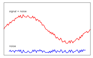
If analog is better, why do we even have digital? The answer is twofold: noise and dynamic range. Noise is always present in a signal. If restricted to a narrow frequency or time band, noise can often be filtered. However, there is always a danger of throwing out useful data along with the noise, especially both are if in a similar frequency range. Here is an example of a signal with easily-filtered noise — their frequencies and amplitudes are quite different.


Dynamic range is the difference between the lowest and highest signal level. A system can’t have an infinite voltage, so there is always some limit to the highest value an analog signal can represent. In contrast, a digital signal can represent arbitrary ranges just by adding more bits (32 bits not enough range? Try 64!)


In the next post, we’ll examine noise in more detail to understand the main difference between digital and analog logic.

Attacking RSA exponentiation with fault injection

A new paper, “Fault-Based Attack of RSA Authentication” (pdf) by Pellegrini et al, is making the rounds. The general idea is that an attacker can disrupt an RSA private key operation to cause an invalid signature to be returned, then use that result to extract the private key. If you’re new to fault injection attacks on RSA, I previously wrote an intro that should help.

The main concept to grasp is that public key crypto is brittle. In the case of RSA’s CRT operation, a single bit error in one multiplication result is enough to fully compromise your private key. We’ve known this since 1997. The solution is simple: validate every signature with the public key before returning it to the caller.

The authors noticed something curious. OpenSSL does verify signatures it generates before returning them, but if it detects a problem, it does not just return an error. It then tries again using a different exponentiation process, and then returns that signature without validating it.

Think about this for a moment. What conditions could cause an RSA private key operation to compute an invalid answer? An innocent possibility is cosmic radiation, bad RAM, etc. In this case, all computations should be considered unreliable and any retried operation should be checked very carefully. The other and more likely possibility is that the system is under attack by someone with physical proximity. In this case, OpenSSL should generate a very obvious log message and the operation should not be retried. If it is, the result should be checked very carefully.

For whatever reason, the OpenSSL programmers decided to retry with fixed-window exponentiation and trust that since there were no published fault attacks for it, they didn’t have to validate its result. This is a foolhardy attitude — not something you want to see in your crypto library. There had been many other fault injection attacks against various components or implementation approaches for RSA, including right-to-left exponentiation. There was no reason to consider left-to-right exponentiation invulnerable to this kind of attack.

Fixed-window exponentiation is a form of sliding window exponentiation. This is just a table-based optimization, where a window (say, 3 bits wide) is moved across the exponent, computing the final result incrementally. While this may be resistant to some timing attacks (but not cache timing or branch prediction attacks), there is nothing that would prevent fault injection attacks.

Indeed, it turns out to be vulnerable. The authors generate a few thousand signatures with single bit-flips in some window of the signature. Then they compare the faulty signatures to a correct signature over the same message. They compute the value for that portion of the private exponent since there are only 2w possibilities for that location if w is the window size in bits. This is repeated until enough of the private key is known.

The method they used to create the faulty signatures was a bit artificial. They built a SPARC system on an FPGA running Linux and OpenSSL. They then decreased the power supply voltage until multiplies started to fail. Since multiplication logic is a relatively long chain, it is often one of the first things to fail. However, a more interesting hardware result would be to attempt this kind of attack on an actual server because FPGAs work differently than ASICs. It might require careful targeting of the right power pins on the CPU. Since power pins are numerous in modern systems, this may be more effective than only modulating the system power supply.

This was a nice attack but nothing earth-shattering. The only thing I was floored by (yet again), was the willingness of crypto implementers to perform unsafe operations in the face of an almost certain attack. Shame on OpenSSL.